- 您现在的位置:买卖IC网 > Sheet目录1994 > DS1689SN+T&R (Maxim Integrated Products)IC RTC SER NV RAM CTRL IN 28SOIC
DS1689/DS1693
12 of 36
Table 2. Periodic Interrupt Rate and Square-Wave Output Frequency
EXT. REG. B
SELECT BITS REGISTER A
E32K
RS3
RS2
RS1
RS0
tPI PERIODIC
INTERRUPT RATE
SQW OUTPUT
FREQUENCY
0
None
0
1
3.90625ms
256Hz
0
1
0
7.8125ms
128Hz
0
1
122.070
s
8.192kHz
0
1
0
244.141
s
4.096kHz
0
1
0
1
488.281
s
2.048kHz
0
1
0
976.5625
s
1.024kHz
0
1
1.953125ms
512Hz
0
1
0
3.90625ms
256Hz
0
1
0
1
7.8125ms
128Hz
0
1
0
1
0
15.625ms
64Hz
0
1
0
1
31.25ms
32Hz
0
1
0
62.5ms
16Hz
0
1
0
1
125ms
8Hz
0
1
0
250ms
4Hz
0
1
500ms
2Hz
1
X
(See Note)
32.768kHz
Note: RS3–RS0 determine periodic interrupt rates as listed for E32K = 0.
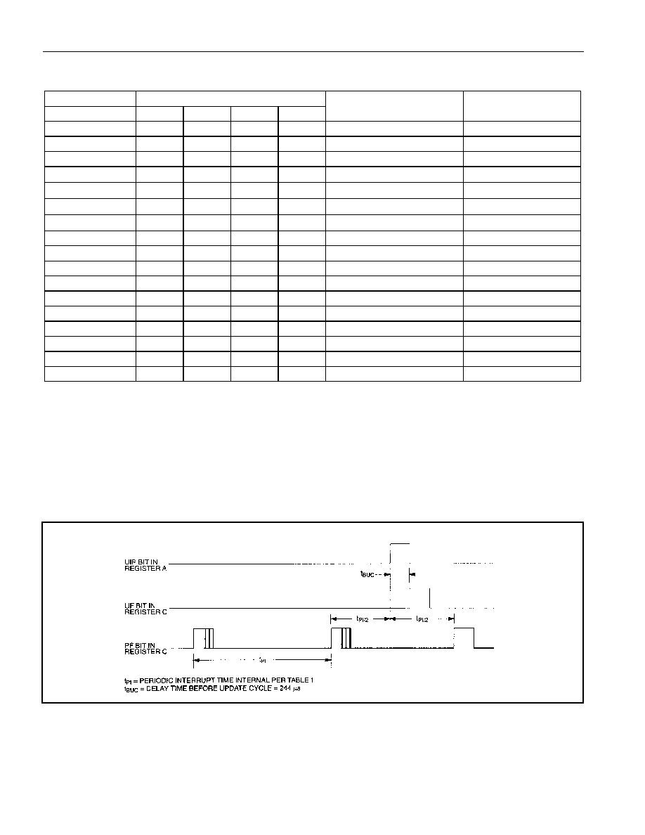
The third method uses a periodic interrupt to determine if an update cycle is in progress. The UIP bit in
Register A is set high between the setting of the PF bit in Register C (see Figure 3). Periodic interrupts
that occur at a rate of greater than tBUC allow valid time and date information to be reached at each
occurrence of the periodic interrupt. The reads should be complete within (tPI / 2 + tBUC) to ensure that
data is not read during the update cycle.
Figure 3. Update-Ended and Periodic Interrupt Relationship
发布紧急采购,3分钟左右您将得到回复。
相关PDF资料
DS17285S-3NT
IC RTC 3V 2K NV RAM 24-SOIC
DS1742-100IND
IC RTC RAM Y2K 5V 100NS 24-EDIP
DS1743P-70+
IC RTC RAM Y2K 5V 70NS 34-PCM
DS1744-70IND
IC RTC RAM Y2K 5V 70NS 28-EDIP
DS1746-70IND
IC RTC RAM Y2K 5V 70NS 32-EDIP
DS1747W-120IND
IC RTC RAM Y2K 3.3V 120NS 32EDIP
DS17887-3-IND
IC RTC 3V 8K NV RAM 24-EDIP
DS1851E-010+
IC DAC DUAL NV TEMP CNTRL 8TSSOP
相关代理商/技术参数
DS1689SN+T&R-W
功能描述:实时时钟
RoHS:否 制造商:Microchip Technology 功能:Clock, Calendar. Alarm RTC 总线接口:I2C 日期格式:DW:DM:M:Y 时间格式:HH:MM:SS RTC 存储容量:64 B 电源电压-最大:5.5 V 电源电压-最小:1.8 V 最大工作温度:+ 85 C 最小工作温度: 安装风格:Through Hole 封装 / 箱体:PDIP-8 封装:Tube
DS1689SN+W
功能描述:实时时钟 RoHS:否 制造商:Microchip Technology 功能:Clock, Calendar. Alarm RTC 总线接口:I2C 日期格式:DW:DM:M:Y 时间格式:HH:MM:SS RTC 存储容量:64 B 电源电压-最大:5.5 V 电源电压-最小:1.8 V 最大工作温度:+ 85 C 最小工作温度: 安装风格:Through Hole 封装 / 箱体:PDIP-8 封装:Tube
DS1689S-TRL
功能描述:IC RTC SER W/NV RAM CTRL 28-SOIC RoHS:否 类别:集成电路 (IC) >> 时钟/计时 - 实时时钟 系列:- 产品培训模块:Obsolescence Mitigation Program 标准包装:1 系列:- 类型:时钟/日历 特点:警报器,闰年,SRAM 存储容量:- 时间格式:HH:MM:SS(12/24 小时) 数据格式:YY-MM-DD-dd 接口:SPI 电源电压:2 V ~ 5.5 V 电压 - 电源,电池:- 工作温度:-40°C ~ 85°C 安装类型:表面贴装 封装/外壳:8-WDFN 裸露焊盘 供应商设备封装:8-TDFN EP 包装:管件
DS1691
功能描述:实时时钟 RoHS:否 制造商:Microchip Technology 功能:Clock, Calendar. Alarm RTC 总线接口:I2C 日期格式:DW:DM:M:Y 时间格式:HH:MM:SS RTC 存储容量:64 B 电源电压-最大:5.5 V 电源电压-最小:1.8 V 最大工作温度:+ 85 C 最小工作温度: 安装风格:Through Hole 封装 / 箱体:PDIP-8 封装:Tube
DS1691 WAF
制造商:Texas Instruments 功能描述:
DS1691/1692 WAF
制造商:Texas Instruments 功能描述:
DS1691A
制造商:NSC 制造商全称:National Semiconductor 功能描述:(RS-422/RS-423) Line Drivers with TRI-STATE Outputs
DS1691AJ/883
制造商:NSC 制造商全称:National Semiconductor 功能描述:(RS-422/RS-423) Line Drivers with TRI-STATE Outputs